• Why not take a moment to introduce yourself to our members?

Rating - 100%
90   0   0
So I read almost every week , as many of you, about new led fixtures being put on market and I'm became more and more convinced to switch from my current t5's lighting to LED. I am trying to read as much as I can before I even think of making a LED fixture myself, but from what I understand right now, it's not THAT hard to build one. I still need some advice though:)
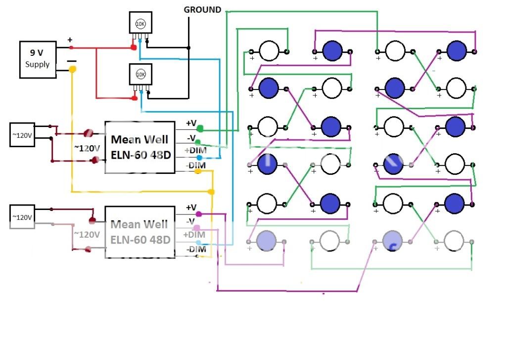
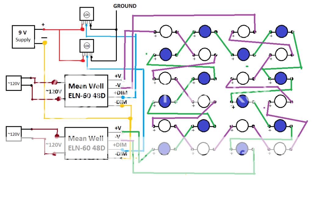
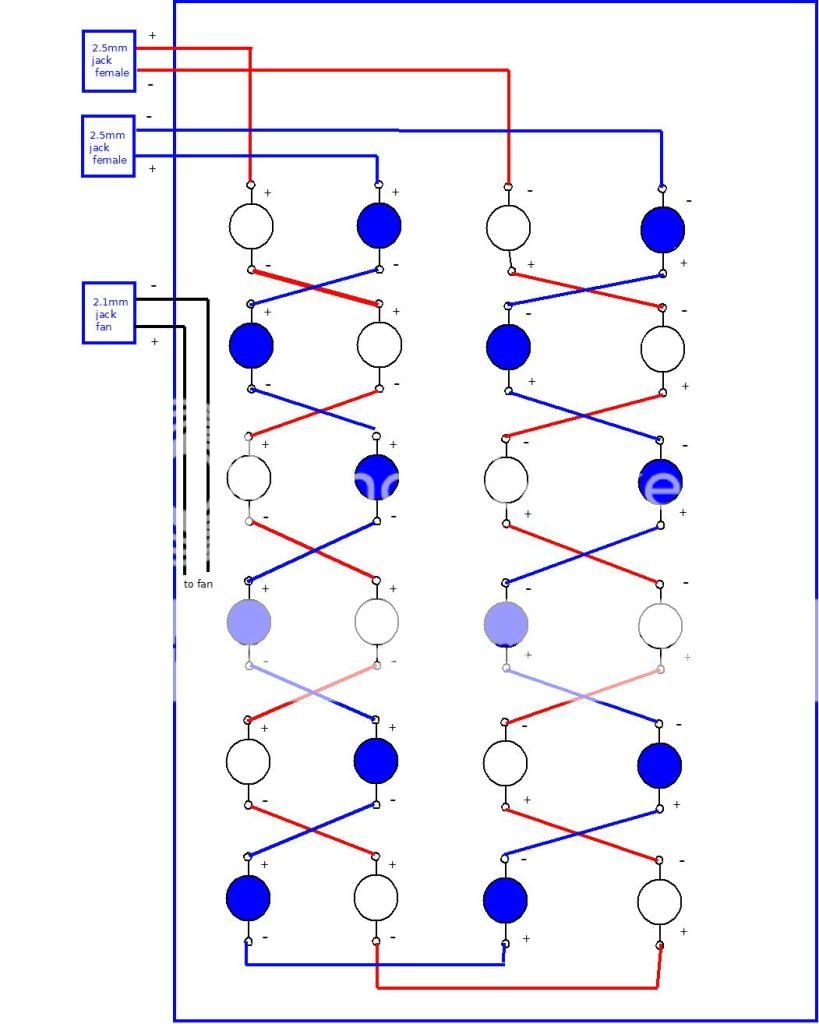
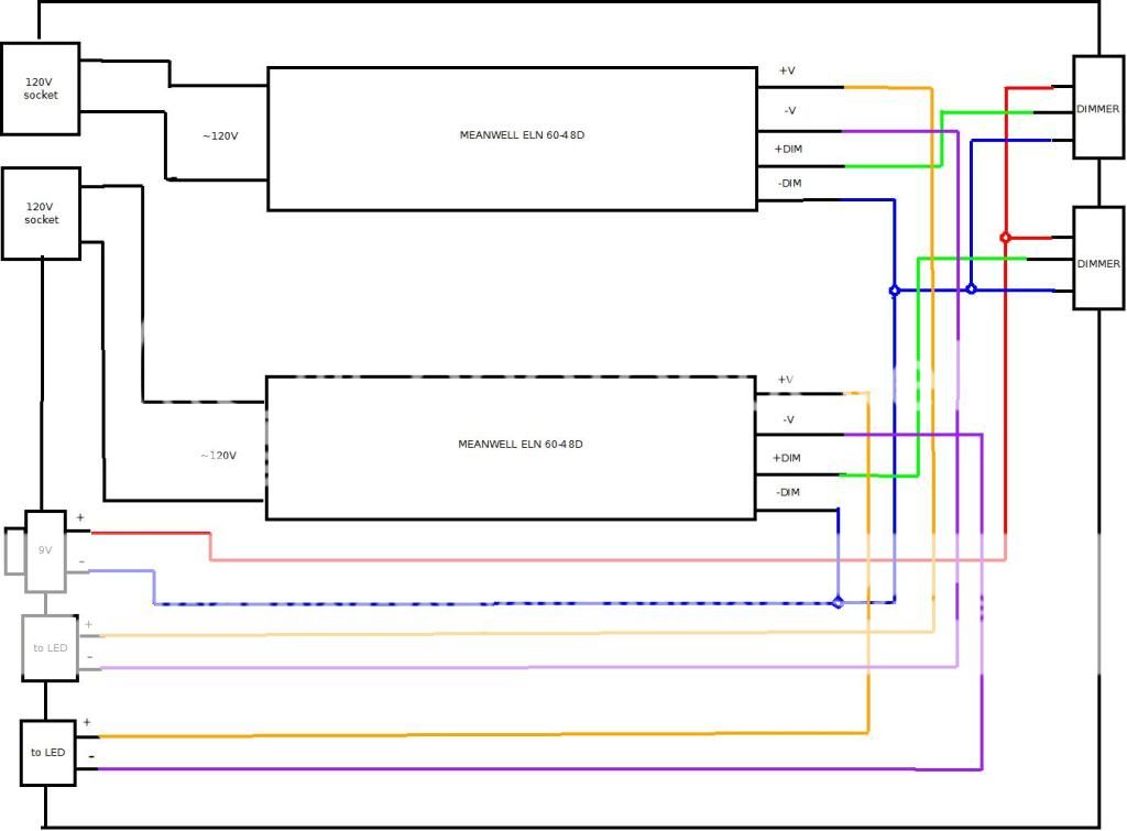
OK, let's start from the beginning- my tank is a Current Solana which has footprint of 20x20. I was thinking of buying this kit http://www.rapidled.com/servlet/the-54/24-Ultra-Premium-LED/Detail. It has 24 3W total, 12 Cool White Cree XP-G R5 LEDs, 12 Royal Blue Cree XR-E LEDs and two 48W Mean Well ELN-60-48D dimmable drivers. I have a couple of questions about them (warning, some of them may be stupid:))
- first of all, is it a good deal or should I buy things separate
-second, even more important- is it gonna be enough light for that tank? I need to light up approximately 16x20 area (rest is back chambers) and would like to use that light also if I ever upgrade to a bigger tank (of course not by itself). Let's say that it may be an sps tank in the future, would it be sufficient? From my early calculations, the light itself would be 10x16 (2" space between leds plus 2" from the edge of housing; leds arranged in 4 rows of 6 leds, 3 white and 3 blue in each row, what do you think?)
- would you recommend a mean well driver? Correct me if I'm wrong, but does this driver need an external dc voltage source or is it built in? And one more thing, the driver is dimmable- does it mean it has a dimmer built in or do I have to solder one to it? If I have to, what kind?

That's all for now but I will definitely have more questions to come. Thank you very much for all your suggestions.
 
Rating - 100%
90   0   0
I am also updating my light to led.i have a 150 gallon tank.if you want i can show you how i am making mine.

Thanks Mike. Where in NJ are you located?


OK guys, I read some more and I think I understand it now a little bit more. I would like you to review and eventually correct me if I'm wrong. Here's the beta diagram of the leds

leds.jpg


So there are two separate circuits for two meanwell drivers, one for white snd one for blue leds. The dimmer is made by using a 9V wallwart that is connected to dimm connectors in the meanwell thru a 10K potentiometer.

Questions:

What kind of potentiometer can I use and can I made two separate boxes, one for dimmer knobs and one for drivers.
What size heatsink would be the best choice and where to buy it?
Did I miss something in the diagram?

Thanks for your help
 

jsvokowest

Experienced Reefer
Location
bayside
Rating - 100%
2   0   0
wondering why are you connecting the + out of the drivers to the - of the LEDs you would be throwing them in reverse bias. Also I weas looking at this data sheet and there is a driver with an optional dimming control. so no need for the pots. They also show you some configurations in which you can run the system in a parallel circuit avoiding the whole string going out. This way if one bulb burns out you can adjust the current and still run lights vs having the whole thing dead.
 

ming

LE Coral Killer
Location
Flushing, NY
Rating - 100%
272   0   0
wondering why are you connecting the + out of the drivers to the - of the LEDs you would be throwing them in reverse bias. Also I weas looking at this data sheet and there is a driver with an optional dimming control. so no need for the pots. They also show you some configurations in which you can run the system in a parallel circuit avoiding the whole string going out. This way if one bulb burns out you can adjust the current and still run lights vs having the whole thing dead.

I think you're right on the first part. The + out of the driver goes to the + on the first LED.

The driver is dimable so he would need to use a pot to manually control the dim option. The dimable ballast has a plastic screw inside the ballast, but that wasn't designed to be used to dim. It was designed to be as a set and forget for your initial output (i.e. to make your full output at 1A instead of a lot higher which could damage your LED's)
Also, if you use the inside screw to dim, you will notice that each ballast may be slightly off (some higher and some lower) on their maximum and minimum setting from the internal screw. They all seem to match the designed range of amps, but may go above and/or below that as well. Once you use a multimeter and set them equal, your pot can adjust it equally as well. Using this Dimmer also allows you to connect to a controller in the future if you wanted in place of the POT

Also, I read on many threads running in parallel is dangerous because if one LED on a strip goes out, all the current goes to the second strip overloading it and burning all the LEDs on that second strip. There are ways around this, which would be by putting multiple fuses wired in which would pop instead, but then why not make it 1 strip to begin with? Its quite easy to test which LED burnt out with two AA batteries
 
Last edited:
Rating - 100%
90   0   0
Oh crap, I messed up with the first line to led and now the whole string is bad I'll try to fix the diagram when I come back, but yes, I'm aware that the first connection from driver's + should go to led's +.
That's weird with the dimmer, cause I've been told by two other people that the wallwart method of dimming worked better for them than lm317 dimmer. Can you point me how to build one as I have no knowledge of that.

BTW I fixed the diagram, what do you think now?

leds-1.png


Now the questions:
-Is this a good deal http://www.rapidled.com/servlet/the-54/24-...mium-LED/Detail, or should I get parts separate?
-should I use any optics- my tank is 20x20" and the display area is approximately 16x20"; the light will be hang approximately 6" above the tank
 

ming

LE Coral Killer
Location
Flushing, NY
Rating - 100%
272   0   0
Test the wallmart to make sure it is truely 9V, under no load and then under a load. I've seen some 12V wallmarts output 16V under no load.
Having the wallmart output more then 10V will damage the ballast. If it tests below 10V, then you'll be fine.
I tried using the LM317 but it seems to overheat on me. I then went with an Apex controller
 

qy7400

Member
Location
Long Island
Rating - 100%
28   0   0
The prices as far as I know are good from rapid led, they match most others who bundle everything.
You'll only need the optics for 18" or deeper but the kits come with them so you could try them out.

Ming brings up good point to check the wall wart, hate to see the driver fry from over voltage. Even better pick up a RKL with the ALC module, you'll have a nice sunrise/sunset and color control for the light.

One more note....none of the kits include a heat sink so you'll need to add that.
 
Rating - 100%
90   0   0
Thanks guys for your help.
I'll make sure the wallwart is keeping 9V constant.
I already have an RKL, but to be clear with you, I dont even know what an ALC module doing. Will it replace my pot dimmers?

I have more questions now:)
-I talked to Marc and saw his led setup and he is using an aluminum plate instead of heatsink and there's no fan on his leds. He said that it works for him but if I put one fan over the plate I would be 100% safe. It seems like a cheaper alternative to heatsink to me, the question is where to get it and will you do it instead of heatsink?
-second thing- I read that meanwhell 48V driver can handle 13 leds so can I add two more leds to the setup making total of 26 or just be safe with 24. I was thinking adding two green or red leds but would like to know your opinion.

Here's the list of things I'm need to build the light, please tell me if I'm missing something

-tools like drill, soldering iron and stuff like that, I have it covered
-the LED kit which comes with

  • 12 Cool White Cree XP-G R5 LEDs

  • 12 Royal Blue Cree XR-E LEDs

  • 12 Cree XR-E Lenses

  • 2 Mean Well ELN-60-48P

  • 1 Arctic Alumina Thermal Adhesive

  • 4 water resistant wire nuts

  • 2 power cords

  • 23 pieces of pre-cut wire
-a heatsink or an aluminum plate + fan for that (what kind of?)
-additional wire (what gauge should I get?)
-two 10K pots
-9V wallwart

Did I miss something
 

jsvokowest

Experienced Reefer
Location
bayside
Rating - 100%
2   0   0
You probably have more experience with the drivers than i do. In respect to the parallel vs series issue. My concern would be that if one bulb would short not create an open circuit the current would rise throughout the entire circuit risking the eventual damage to further LEDS as well as a situation without lighting for a given period of time since the entire string would be out whether it was a short or an open circuit. However in a parallel situation you would still have lighting until you could repair the unit. The Voltages across each branch would still remain the same whether there was a problem or not and each branch could be controlled for resitance with a pot. I am also wondering why the 9 volt power supply is needed as a pot could be wired as a rheostat to limit the current which would limit the flow of electrons dimming the lights. Is that 9 volts to power a dimming circuit?
 

Widdy

Moderator
Vendor
Rating - 100%
75   0   0
The ALC module will replace your pots, the ALC module will also provide a way to automatically raise/dim your lights; giving you a sunrise/sunset effect.

http://www.digitalaquatics.com/saltwater/ALC

According to the link, it'll give you 2x 1-10vDC. So you can put your whites on 1 port and your blues on the other.

My original DIY fixture (24 LEDs driven by buckpucks) I bought a heatsink from heatsinkusa.com. But it was big and clunky but worked well... the next fixture (26 LEDs driven by 2 Meanwells) I used 1x1" aluminum tubing from Home Depot + 2 120mm fans, zero heat. My next fixture to go along with my tank upgrade (36x24x20), I'm using aluminum plates (approximately 1" thick). Will hold 13 LEDs per strip, total of 65 LEDs and 5 Meanwells + 4x 120mm fans. Total weight, not including the Meanwells, should be about 4-5lbs if that much.

Mike @ RapidLEDs is a great guy to deal with... he answered any questions I had, and I'm sure he'll do the same for you. Hit him up at [email protected] should you need any info. G'luck!
 

ming

LE Coral Killer
Location
Flushing, NY
Rating - 100%
272   0   0
You probably have more experience with the drivers than i do. In respect to the parallel vs series issue. My concern would be that if one bulb would short not create an open circuit the current would rise throughout the entire circuit risking the eventual damage to further LEDS as well as a situation without lighting for a given period of time since the entire string would be out whether it was a short or an open circuit. However in a parallel situation you would still have lighting until you could repair the unit. The Voltages across each branch would still remain the same whether there was a problem or not and each branch could be controlled for resitance with a pot. I am also wondering why the 9 volt power supply is needed as a pot could be wired as a rheostat to limit the current which would limit the flow of electrons dimming the lights. Is that 9 volts to power a dimming circuit?

If 1 LED goes out, it would most likely break the circuit, but if it doesn't, 1 LED out of 12 or 13 would cause the remaining 11 or 12 to go up by about 8%. The remaining LED's would become slightly brighter and run slightly hotter, I tested these LED's to run up to 1.7A but only for a few seconds. It just gets really hot very fast and very bright. Most people suggest the upper limit of these LED's to be 1A, and the major reason why LED's go bad quick is from the heat. With proper cooling, running the LED's at 1.08A wouldn't be such a big deal IMO and hopefully he'll notice the burnt LED soon, also with the assumption hes running it at maximum of 1A. Some people never even run it at full because it bleaches their corals from the intensity. Also, I keep a couple spare bulbs handy just in case one burns out, never had any go bad yet from testing and soldering.

The 9V is only to send a 0-10V signal to the ballast... or 0-9V in this case.
The ballast will know that 10V is to send the output at max (you can adjust the plastic screw in the ballast so 9V is 1A with a multimeter).
I think you're suggesting to just limit the power directly to the LED's itself instead of letting the driver do that. That sounds like it should work, but then I think there is wasted electricity that way... I could be wrong about the last statement.

Also, I think you want 2 Mean Well ELN-60-48D
The P versions want a PWM signal
The D versions want a 0-10V signal
 
Last edited:
Rating - 100%
90   0   0
I think I'll just solder the leds in row, that way I would know instantly that one of them went of.

Also, I think you want 2 Mean Well ELN-60-48D
The P versions want a PWM signal
The D versions want a 0-10V signal

Yeah, I just copied/paste from their website and missed that. I would order the "D" model.

Anyway, I think I'm about ready to order and I need some advice:

-what gauge and kind of wire should I order
-I need a 4-40 tapping kit correct? What size machine screws will go with that?
-can I use the regular HD soldering wire or would you recommend something else
-one most important thing- I was thinking of using an 1/4 or 3/8 aluminum plate instead of heatsink and glue some old computer heatsinks on top to cut costs (there will be one fan cooling the plate)- do you know where to get that kind of plate locally?
 
Rating - 100%
90   0   0
OK guys/gals, I did a semi-pro diagram of what I'm trying to achieve, please tell me if I'm doing things right.

First, the LEd board with LEDs arranged so there's minimum wiring. the cables will run to two dc power jacks and then to driver box. There's gonna be one separate input to power up a cooling fan

ledboard.jpg


Now the driver box. Quick explanation- two ~120 sockets to plug standard computer PS cable-that's gonna power up the drivers. Then another input for 9V regulated wallwart. The pots are on the other side and there's two outputs that go to LED board.

driverbox.jpg
 

joseney21

FDNY MEDIC
Location
Bronx, New York
Rating - 100%
26   0   0
i dont know how far along you are but here are some tips anyway...

i've tested many 9v wall warts and none were nine volts or less. they all put out varying voltages depending on load, if you try to regulate the wall wart using a pot your current will also vary when you adjust them...it would be very convenient for you to get yourself a volt regulator off ebay for $7. look for this on ebay...there is a guy that ships from the US but his price is off by about $80 right now, i think it was a typo... look for one with an input voltage between 5-24v and output from 2-12 (they come with a pot to adjust down to ten.
LM317 Adjustable Voltage Regulator Prototype Module USA


I wouldn't tap, i would use thermal epoxy. it's very easy, nowhere near as time consuming as drilling and tapping and it is very easy to remove burnt LEDs.

check out the prices for LEDs at etgtech.com and check the prices for meanwells at CDI.com (i think)
 

joseney21

FDNY MEDIC
Location
Bronx, New York
Rating - 100%
26   0   0
ming, they shipped the meanwells when they got them in stock. they were good with communication and price. as long as youre willing to wait until they have them in stock it's a pretty good deal. for me it was about 1-1.5 months.
 

Sponsor Reefs

We're a FREE website, and we exist because of hobbyists like YOU who help us run this community.

Click here to sponsor $10:


Top